Introduction to Fuses
A fuse, also known as a fuse link, is defined as a component installed in an electrical circuit to ensure the safe operation of the circuit. Under specified voltage conditions, current passes through the fuse element.
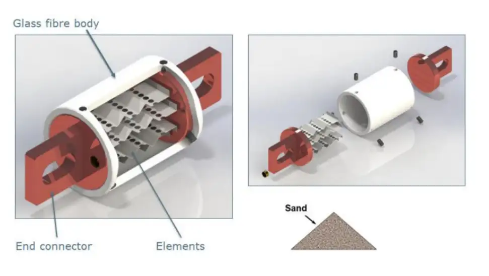
Utilizing the thermal effects of the current, when the accumulated heat reaches a certain level, the specific part (narrow section) of the fuse element melts and disconnects within the prescribed time, thereby safely interrupting the fault current.
Working Principle of Fuses
When current flows through a conductor, the conductor heats up due to its inherent resistance. The heat generated follows the formula Q=I²Rt, where Q is the heat generated, I is the current flowing through the conductor, R is the conductor’s resistance, and t is the time the current flows through the conductor. Based on this formula, the working principle of a fuse can be understood as follows:
As current flows through the fuse, it heats up, and the amount of heat generated increases with time. The magnitude of the current and resistance determines the rate of heat generation, while the construction of the fuse and its installation conditions determine the rate of heat dissipation.
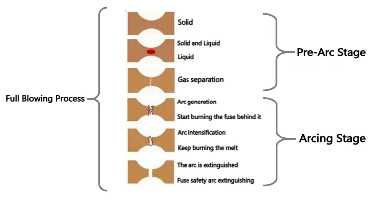
If the rate of heat generation is less than the rate of heat dissipation, the fuse will not melt. If the rate of heat generation equals the rate of heat dissipation, the fuse will not melt for a considerable period. However, if the rate of heat generation exceeds the rate of heat dissipation, the accumulated heat will increase. Due to its specific heat capacity and mass, this increase in heat manifests as a rise in temperature. When the temperature rises above the melting point of the fuse, the fuse undergoes melting and interruption.
How to Choose a High Voltage Fuse?
1. Confirm whether the fuse is used for an AC circuit or a DC circuit.
It is crucial to determine whether a fuse is intended for use in an alternating current (AC) circuit or a direct current (DC) circuit. Incorrectly using an AC fuse in a DC circuit or vice versa may lead to accidents.
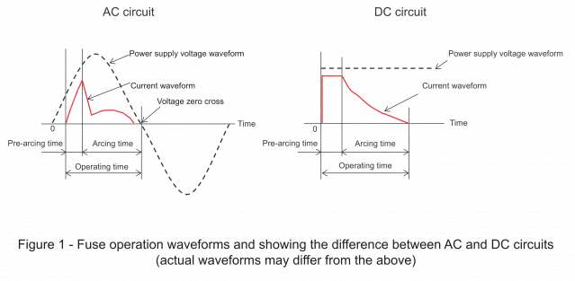
In AC circuits, the arc discharge tends to extinguish when the power voltage becomes zero. However, as the DC voltage does not reach zero in DC circuits, there is a risk that arc discharge may not extinguish, potentially causing fuse damage (refer to Figure 1).
Therefore, for DC circuits, only DC fuses should be selected, and only AC fuses for AC Circuit!
2. Rated Voltage (Un): The nominal rated voltage of the fuse.
This term is introduced from the perspective of the safe use of fuses, indicating the highest operating voltage of the circuit in which the fuse is installed while maintaining a safe working condition. This implies that the fuse should only be placed in circuits where the working voltage is less than or equal to the rated voltage of the fuse for it to function safely and effectively. Otherwise, continuous arcing and circuit damage may occur when the fuse melts.
For example, a 250V fuse can be used in circuits with voltages of 125V or lower.
3. Rated Current (Mainly for small current selection): The nominal rated current of the fuse.
It represents the current level that the fuse can withstand under normal operating conditions, not the operating current. The correct choice of the rated current value must consider the following:
- For UL specifications with weak overload capacity, the rated current In = Ir/Of, where Ir is the circuit’s operating current, and Of = 0.75 is the current reduction factor of the fuse. For example, if the circuit’s operating current Ir is 1.5A, a fuse of 2A should be selected (1.5/0.75 = 2A).
- For IEC specifications with strong fuse overload capacity, no reduction is needed, i.e., Ir = In.
4. Ambient Temperature (Mainly for small current selection):
The current-carrying capacity of a fuse is determined through experiments conducted at an ambient temperature of 25°C. However, these experiments are influenced by changes in ambient temperature: as the ambient temperature increases, the operational temperature of the fuse rises, leading to a reduced current-carrying capacity and shorter lifespan. Temperature derating needs consideration in such cases (refer to the diagram below).
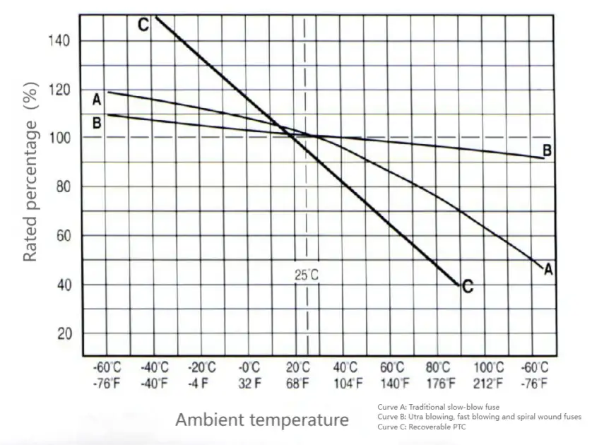
For instance, selecting a fast-acting fuse operating at 90°C in a small environment with a current of 1.5A, as depicted in the diagram on the right, its temperature reduction factor (Tf) is 95%.
If following IEC specifications: In = In / Tf = 1.5 / 0.95 = 1.58, hence recommending a rated current of 1.6A or 2A.
If following UL specifications: In = In / (Of * Tf) = 1.5 / (0.75 * 0.95) = 2.1, thus recommending a rated current of 2.5A.
5. Maximum Breaking Capacity (A/kA):
The maximum breaking capacity of a fuse refers to the maximum current that a fuse can safely interrupt or disconnect under specified conditions without causing damage. It is essentially the maximum fault current that the fuse can handle and safely interrupt.
Breaking capacity stands as the primary safety indicator for fuses. Different fuses possess varying breaking capacities based on their design and intended applications. A high breaking capacity is crucial to ensure the fuse can safely disconnect the circuit during a fault or overload condition without causing any unsafe occurrences: such as shattering, burning, splashing, exploding, or damaging surrounding persons or other components.
For example, a fuse with a breaking capacity of 10,000 amperes (10 kA) can safely interrupt a fault current of up to 10,000 amperes without sustaining damage.
6. Protection Categories::
According to IEC standards, fuse protection categories are typically divided into “g-type” and “a-type” (refer to the table below)::
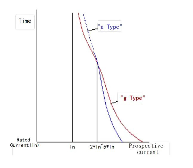
“g-type”: Full Range Protection – Capable of interrupting any current between the melting of the fuse link and the rated breaking capacity. Suitable for protecting against overload and short-circuit currents. Can independently serve as protection for the entire current range.
“a-type”: Partial Range Protection – Capable of interrupting any overcurrent between the minimum breaking current and the rated breaking capacity. Suitable for short-circuit (backup) protection. Requires combination with other protective devices to provide comprehensive overcurrent protection.
General characteristics of categories “g” and “a” with the same tube, voltage, and current are compared below:
| Type | Application | Breaking Range | Remarks |
| gG | General protection purposes– Distribution line protection |
Full Range | Common protection wires, motors, transformers, capacitors, switches, etc., |
| gM | Motor circuit protection – time delay | Full Range | Rarely used for other equipment protection |
| aM | Motor circuit protection – time delay | Partial range (Backup) |
Rarely used for other equipment protection |
| gN | Generally used in North America for wire protection | Full Range | General protection compatible with UL standards |
| gD | North American General Purpose Delay | Full Range | General protection compatible with UL standards |
| aR | Semiconductor protection | Partial range (Backup or short circuit protection) |
Protect semiconductor devices or systems, generally fast, low I²t, special shock-resistant and extremely slow |
| gR | Semiconductor and wire protection | Full Range | Low I²t |
| gPV | Photovoltaic system protection, generally fast | Full Range | Photovoltaic systems, low inductive-capacitive circuit protection |
| aR-VSI | Inverter capacitor current protection | Short circuit protection | Very low I²t, suitable for breaking capacitive circuits |
7. Fusing Characteristics::
Fuse characteristics, also known as time/current characteristics, I-T characteristics, or ampere-second characteristics, are often represented using curve graphs:
The fuse characteristic curve illustrates the functional relationship between different current loads and their corresponding fuse-blowing times, providing a reference for selection (refer to the graph)
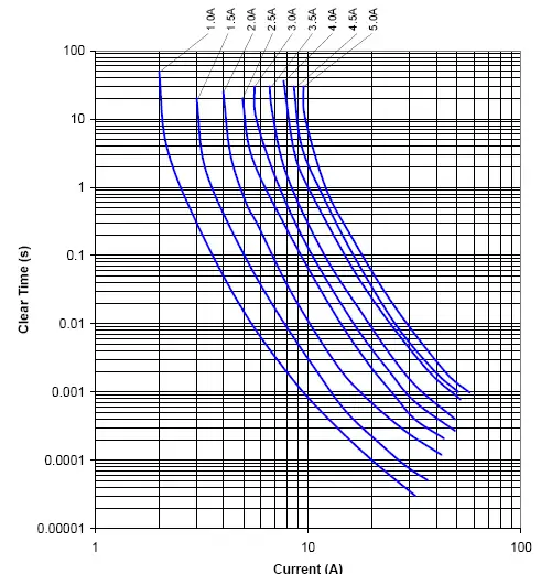
Fuses need to have a certain overload capacity:
- According to UL specifications, the maximum non-blowing current for a fuse is 110% In.
- According to IEC specifications, the maximum non-blowing current for a fuse is 113% In or 120% In.
Fuses are also required to burn out promptly when subjected to overcurrent beyond the specified limit:
- According to UL specifications, the minimum blowing current for a fuse is around 135% In.
- According to IEC specifications, the minimum blowing current for a fuse is around 145% In.
8. Melting Energy (I²t):
The melting energy value refers to the energy value when the fuse link melts, indicating the fuse’s ability to withstand surges. Here, I am the overload current, and t is the blowing time. The energy required for the fuse blowing (If²t) and the energy released by the surge pulse (Ir²t) determines whether the fuse will blow. If Ir²t > If²t, the fuse blows; if If²t < Ir²t, the fuse can withstand the surge.
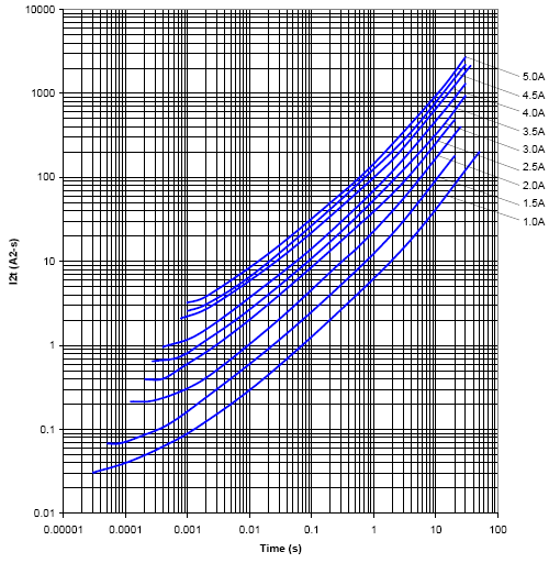
The blowing time of a fuse is related to factors such as the heat generated by the current, heat dissipation conditions, and the thermal capacity characteristics of the fuse. Many factors can influence the blowing time of a fuse, so the If²t values for a fuse are not constant at different interrupt currents or interrupt times.
The If²t-t curve reflects the If²t values of the fuse at different blowing times (see the graph below), similar to the fuse characteristic curve. It serves as a reference for designers when selecting fuses.
9. Product Life/Durability::
The lifespan of a fuse is typically long, and in the absence of faults, it is nearly synchronous with the lifespan of the equipment.
The testing method for the lifespan of small tubular fuses according to IEC specifications involves the following steps: under direct current (DC) power conditions, the fuse is subjected to a current of 1.20 In (or 1.05 In) for one hour, followed by disconnection for 15 minutes. This cycle is repeated continuously for 100 cycles. Finally, the fuse is subjected to a current of 1.5 In (or 1.15 In) for one hour. Throughout this process, there should be no blowing or other abnormal phenomena.
10. Installation Method:
Panel Mounting: Fuse boxes, fuse sockets, etc.
Base Mounting: Fuse clips, fuse clip sockets, etc.
Printed Circuit Board (PCB) Mounting:
- Through-hole Mounting (Wave Soldering): Radial leads, axial leads, etc.
- Surface Mounting: Multilayer monolithic, thin-film type, etc.
Suspended Mounting: Fuse holders.
External Dimensions:
- Tubular: Diameter X Length.
- Miniature: Aperture X Pitch.
- Surface Mount: Solder pad – Length X Width, the distance between ends.
11. Safety Certificate
CE

CE certification is a conformity certification mark in the European Common Market. CE stands for “Conformité Européene” (European Conformity) and serves as a certification mark used by member countries of the European Union (EU) to indicate that products sold in their markets comply with European regulations. CE certification is voluntary for manufacturers and aims to ensure that products meet the requirements of European regulations to guarantee consumer safety, health, and environmental protection.
UL

UL certification is a product safety certification issued by Underwriters Laboratories Inc. (UL), a leading global independent safety science company specializing in product safety testing and certification. The purpose of UL certification is to ensure that products comply with relevant safety standards, providing manufacturers with confidence in selling their products in the market.
cUL

cUL certification refers to certification issued by the Canadian Standards Association (CSA). The cUL mark indicates that a product has been certified by CSA and complies with relevant standards and requirements in Canada. cUL certification typically involves safety and performance testing for electrical and electronic products. This certification is an essential requirement for selling products in the Canadian market and is widely recognized in other countries and regions as well.
CSA

CSA is the abbreviation for the Canadian Standards Association, which is the authoritative certification body for electronic and electrical products in Canada. Electrical products certified by this organization are allowed to be freely sold in the Canadian market. Products certified by CSA can only be sold in the Canadian market, and to enter the U.S. market, they must also obtain UL certification from the United States.
TÜV

TÜV certification is a product certification issued by the German organization Technischer Überwachungsverein (TÜV). TÜV is a leading global independent third-party technical inspection and certification body. This certification typically covers the safety, quality, and performance aspects of a product, ensuring its compliance with relevant standards and regulations. Products that receive TÜV certification can enhance their credibility and competitiveness in the market, particularly in Germany and other European markets.
RoHS

RoHS certification refers to the certification of products that comply with the European Restriction of Hazardous Substances Directive (RoHS Directive). The RoHS Directive is a regulation established by the European Union to restrict the content of certain hazardous substances used in electronic and electrical equipment, aiming to reduce the negative impact on the environment and human health.
REACH

REACH (Registration, Evaluation, Authorization, and Restriction of Chemicals) is a regulation established by the European Union concerning chemicals. The REACH regulation came into effect in 2007 with the aim of safeguarding human health and the environment while encouraging businesses to use chemicals more responsibly.
12. Standards Compliance
- UL 248-1 Underwriters Laboratories Inc. Standard For Safety
- IEC 60269 (GB13539) – Low Voltage Fuses:
- IEC 60947 (GB14048) – Low-Voltage Switchgear and Controlgear:
- IEC 60947-3 (GB14048-3) – Switches, Disconnectors, Switch-Disconnectors, and Fuse Combination Units
- IEC 61818 – Application Guide for Low-Voltage Fuses:
- IEC 61459 – Coordination between Fuses and Contactors/Motor Starters:
Common Failure Mode Analysis of Fuses
- Undersized Rated Voltage Selection, Circuit Inductance Exceeds Standard Test Conditions: If the circuit breaking voltage is higher than the rated voltage of the fuse or if the inductance exceeds standard test conditions, the fuse may fail to reliably interrupt, leading to explosion and arcing.
- Undersized Rated Current Selection: Insufficiently rated current may cause the fuse to blow or reduce its lifespan due to heating and impact currents in the circuit.
- Oversized Rated Current Selection: If the fuse is oversized for certain overcurrents, it may fail to operate or operate too slowly, causing damage to other components.
- Overcurrent < “a” Type Partial Protection Range: The fuse may not reliably blow for overcurrents within the “a” type partial protection range.
- Improper installation or high contact resistance can lead to overheating and damage.
- Mechanical disturbances exceeding fuse design standards may damage or compromise the fuse’s operational conditions.
- Actual Short-Circuit Current Far Exceeds the Fuse’s Rated Breaking Capacity: The fuse may not reliably interrupt the short-circuit current.
- The installation distance between fuses is too close, or the influence of other heating components prevents reasonable heat dissipation and shortens the service life;
Recommendations to Avoid Fuse Failures and Ensure Reliable System Protection
- Selection: Provide accurate circuit operating parameters to assist in proper fuse selection for effective protection.
- Choose Quality Manufacturers: Select manufacturers with high-quality materials, process quality, thorough inspections, and consistency in meeting requirements.
- Product Testing and Application Testing: Conduct thorough testing of products and their applications to ensure reliability.


